top of page
PI2-EX
Hardware Attachments


Fig. 1 - Raspberry Pi2 40-pin GPIO with all labels.
Fig. 2 - LCD labels.
Fig. 3 - 7-segment display and first mcp 23S17IC labels.
Fig. 4 - Second mcp connected to digital inputs and switches. Labels for ULN also presented.
Fig. 5 - ULN labels and connections to LEDs, optocouplers and relays.
Fig. 6 - Circuit [1] - Schematic of the first circuit used to test SPI.
Fig. 7 - Circuit [2] - Schematic of the circuit used to test the optocoupler and the relay.
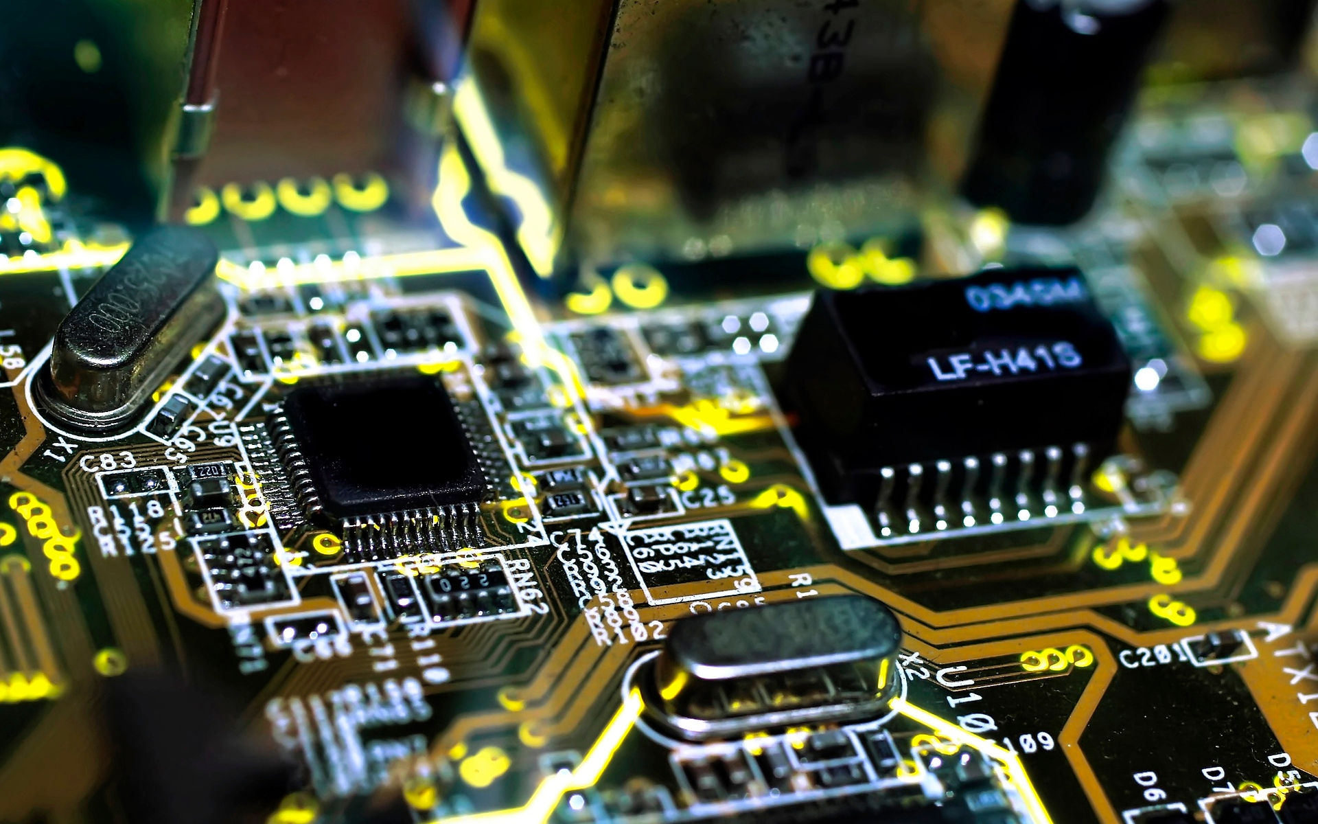
Fig. 8 - Complete PCB layout ready for manufacteur - hardware of the Raspberry pi expansion board.
2 - SPI communication protocol test circuit
3 - Optocoupler and relay test circuit
4 - Expansion board PCB layout
1 - Schematic of the expansion board
bottom of page