PI2-EX
Software Attachments
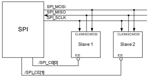
In Stardard SPI master mode the peripheral implements the standard 3 wire serial protocol.
Figure 1 - SPI Master Typical Usage.
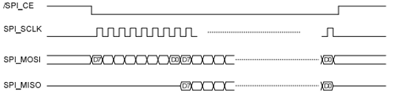
Each SPI cycle is processed as showed on Figure 2.
Figure 2 - SPI Master Typical Usage.
Notes on Figure 2:
-
Slave enables itself onto SPI_MOSI only when it's outputting data.
-
Different SCLK polarity and phase values are possible. Case illustrated is CPOL = 0, CPHA = 0.
-
Data is transmitted MSB first.
-
Transactions can be from single byte to several bytes.
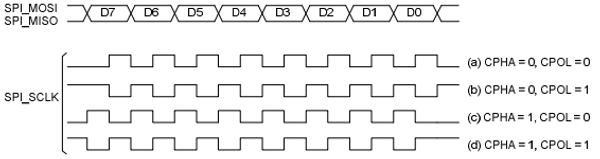
Figure 3 shows the different clock polarity/phase combinations.
Figure 3 - SPI clock polarity/phase combinations.
The protocoll was implemented through the bcm2835_spi_transfernb function. The bcm2835_spi_transfernb function transfers any number of bytes to and from the currently selected SPI slave. Asserts the currently selected CS pins (as previously set by bcm2835_spi_chipSelect) during the transfer. Clocks the len 8 bit bytes out on MOSI, and simultaneously clocks in data from MISO. The data read read from the slave is placed into rbuf. rbuf must be at least len bytes long.
void bcm2835_spi_transfernb (char * tbuf, char * rbuf, uint32_t len);
Parameters:
-
[in] - tbuf, Buffer of bytes to send.
-
[out] - rbuf, Received bytes will by put in this buffer.
-
[in] - len, Number of bytes in the tbuf buffer, and the number of bytes to send/received.
In order to increase efficiency, the SPI communication could have been implemented through a task, by reading from a FreeRTOS FIFO and writing to another.
LCD
7-segment display
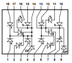
The 7-segment display used is a common cathode, which means all the cathods of the 7-segment display are connected directly together and, in order to toggle the respective LED, the 7-segment respective input pin should be connected to ground. Figure 1 shows the 7-segment common cathode internal citcuit.
Figure 4 - Common cathode double 7-segment display circuit.
The values to send in order to set the right bits on the 7-segment displays are shown on the following table.
Table 1 - 7-segment digit encoded digits.
Functions used on the 7-segment display are showed below.
void semb_7_segment_init(void) {
mcp23s17_write_reg( 0x00, MCP23S17_IODIRA, MCP23S17_ADDRESS + 2 );
mcp23s17_write_reg( 0x00, MCP23S17_IODIRB, MCP23S17_ADDRESS + 2 );
}
void semb_7_segment_set_digit(int num, int digit) {
int i = 0;
for (i = 0; i < 8; i++) {
mcp23s17_write_bit(!(DISP_7SEG_ENCODING_gfedcba[num]>>i & 0x01),
segment[i+digit][PIN],
segment[i+digit][PORT],
MCP23S17_ADDRESS + 2);
}
}
Here's a link to all the code used on the project, available on our repository on GitHub.
2 - SPI communication protocol implementation
1 - MCP available functions
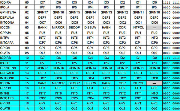
The first thing to do in order to implement the software for the expansion board is to define all the mcp functions in order to communicate between peripherals and the raspberry pi. The MCP23x17 can be configured to operate in 8-bit or 16-bit modes via control register IOCON.BANK=0 or IOCON.BANK=1, respectively. The control registers available are shown below.
Table 1 - control register of MCP23X17 on 16-bit mode.
The implemented functions to work with MCP comprises initialization, registers reading/writing, bit reading/writing, and interrupt related functions. All these functions are presented below.
Rreturns 0 in case of success, otherwise returns an error code.
int mcp23s17_init(int chip_select);
Returns the 8 bit value from the register specified. Must also specify which hardware address. It receives the register to read from (ex.IODIRA, GPIOA), and the hardware address of the MCP23S17.
uint8_t mcp23s17_read_reg(uint8_t reg, uint8_t hw_addr);
Writes an 8 bit value to the register specified. Must also specify which hardware address. It receives the data to be written, the register to write to (ex.IODIRA, GPIOA), and the hardware address of the MCP23S17.
void mcp23s17_write_reg(uint8_t data, uint8_t reg, uint8_t hw_addr);
Reads a single bit from the register specified. Must also be specified the hardware address. It receives the bit number to read, the register to read from (ex.IODIRA, GPIOA), and the hardware adress of the MCP23S17.
uint8_t mcp23s17_read_bit(uint8_t bit_num, uint8_t reg, uint8_t hw_addr);
Writes a single bit to the register specified. Must also be specified the hardware address. It receives the data to write, the bit number to write to, the register to write to from (ex.IODIRA, GPIOA), and the hardware adress of the MCP23S17.
void mcp23s17_write_bit(uint8_t data, uint8_t bit_num, uint8_t reg,
uint8_t hw_addr);
Enables interrupts and exports to the GPIO connection of the MCP23S17. Return int 0 if succeded.
int mcp23s17_enable_interrupts();
Disables interrupts and exports to the GPIO connection from the MCP23S17. Returns 0 if succeded.
int mcp23s17_disable_interrupts();
Waits for an interrupt from MCP23S17 or until timeout is reached. This method does not reset the interrupt. Calling this method twitce in a row without reading the input register will cause it to aleays wait for the timeout value, regardless of button press. It receives the timeout value in ms to wait, -1 will define timeout to infinite.
int mcp23s17_wait_for_interrupt(int timeout);